Selection Tools, Controls, and Output
Each tool is described on its own page. This page explains the ways they are similar.
- Click an editing tool, and a selection box is shown around the point cloud/mesh models, with help text at the bottom. The selection box or plane shows “live” results: you can check and uncheck Show External Mesh to toggle visibility of data outside the selection.
- Cropping Tool

To delete all points or surfaces within a selection box.- Clipping Tool
To delete individual surfaces within a selection box, without the visual distraction of the external mesh or the selection box.- Surface Flipping and Triangle Winding

To optimize the model for virtual reality, select surfaces to flip, so they are front-facing.- 2D Slice
Create floor plan of whole model. A selection plane is displayed across the middle of the model, with a box frame for guidance.- Orthographic Images
Create ortho images of one or many faces of the model. The faces of the selection box are labeled Left, Right, Front, Back, Top, Bottom.

- Tilt, rotate and zoom to find the ideal viewing angle:
Set Orbit Point: Double click.
Rotate: Press and hold left mouse button outside the selection box, and drag.
Zoom: Scroll mouse wheel.
Pan: Press and hold middle mouse button down and drag.
To reset the position of the model and the selection box or plane, click Reset.
- Adjust the selection box or plane, without moving the model. When you hover over a face it darkens, then left click and hold the mouse button to drag the face in or out from the model.
- Move: Press and hold Ctrl, then press and hold left mouse button on a face and drag.
To drag an obscured face behind the model, use Shift (instead of Ctrl).- Reset: Press Space to revert to the default selection box/plane.
- Toggle visibility: Press V to show/hide the selection box/plane.
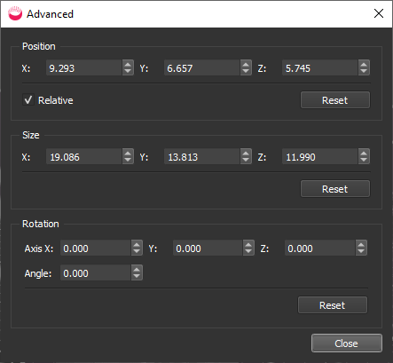
- For Clip, Crop, Slice and Ortho images, you can click Advanced to open a dialog where you adjust the X, Y, and Z values and rotation directly:
Click Close to use those values and return to the main screen.
- When you have selected what you want, click OK, which opens a dialog to define the output. This is different for each tool.
- Check the settings and click OK to close the dialog and create the output.
.
- Cropped point clouds and mesh models are stored in the selected scan folder’s Point Clouds or Mesh Models folder, respectively. Display in a viewport tab to do further editing.
- Ortho images are 2D raster images, stored in the project’s Ortho Images folder. If you double click one in the Project Explorer, it will open in a new tab, but you cannot edit it in PointFuse.
- 2D slices are stored in the selected scan folder’s Plans folder. If you double click one in the Project Explorer, it will open in a new tab, but you cannot edit it in PointFuse.
- Select a different part of the point cloud or mesh model, or close the tool.